29 min to read
Network Topology Models Complete Guide - From Hub-and-Spoke to Mesh
Master network topology design patterns with comprehensive analysis and cloud implementations
Overview
Network topology refers to the physical or logical connection structure between nodes in a computer network. The correct topology selection directly impacts network performance, scalability, cost, and management complexity.
This guide provides comprehensive comparative analysis of core topology models in modern network design, exploring their characteristics and application scenarios in depth. We focus particularly on the Hub-and-Spoke model, which has gained attention in cloud environments, from a practical perspective.
Modern cloud architectures demand sophisticated network topologies that can handle distributed workloads, provide security isolation, and scale efficiently. Understanding the nuances of different topology patterns enables architects to make informed decisions that align with business requirements and technical constraints.
Understanding Network Topology Fundamentals
Topology Classification System
Network topologies are broadly categorized into physical and logical topologies, each serving distinct purposes in network design.
Physical Topology Characteristics
- Actual cable and equipment placement
- Hardware connection structure
- Geographic location and distance considerations
Logical Topology Characteristics
- Data flow and communication paths
- Determined by protocols and algorithms
- Can be designed independently of physical structure
Topology Design Principles
Effective network topology design requires consideration of the following principles:
| Design Principle | Definition | Key Metrics | Impact on Architecture |
|---|---|---|---|
| Scalability | Complexity increase rate when adding nodes | Linear vs Exponential growth | Future expansion capability |
| Reliability | Fault tolerance and recovery mechanisms | MTBF, MTTR, Availability % | Redundancy requirements |
| Performance | Latency, bandwidth, and throughput | RTT, Mbps, PPS | Application response times |
| Cost Efficiency | Construction and operational costs | CAPEX, OPEX per connection | Budget allocation strategy |
| Management Complexity | Operations and maintenance difficulty | Admin overhead, troubleshooting time | Operational procedures |
Hub-and-Spoke Model Deep Dive
Basic Structure and Concepts
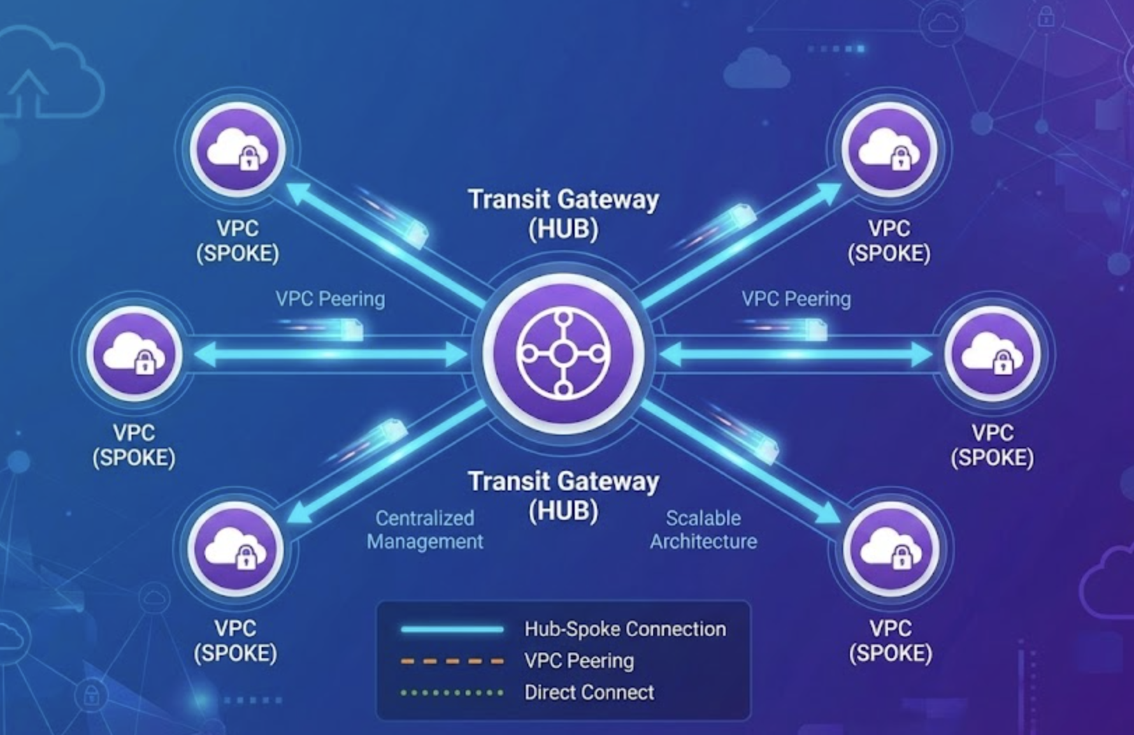
The Hub-and-Spoke model features a central hub through which multiple spokes are connected. Named after a bicycle wheel’s central hub and spokes, it represents the quintessential centralized network architecture pattern.
Mathematical Analysis of Hub-and-Spoke
Understanding the mathematical properties of Hub-and-Spoke topology reveals its efficiency advantages:
Connection Complexity
- n nodes connection: n links required
- Time complexity: O(n)
- Space complexity: O(n)
Comparative Analysis
- Mesh topology: n(n-1)/2 = O(n²)
- Hub-and-Spoke: n = O(n)
For example, connecting 10 nodes:
- Mesh topology: 45 connections
- Hub-and-Spoke: 10 connections
Hub-and-Spoke Advantages
1. Excellent Scalability
Adding new nodes requires connection only to the hub, with no impact on existing connections. This provides linear scalability advantageous for large-scale network construction.
2. Centralized Management
All traffic passes through the hub, providing benefits such as:
- Unified security policy application
- Centralized monitoring and logging
- Consistent routing policies
- Simplified network management
3. Cost Efficiency
Linear increase in connections makes cost prediction easy and eliminates redundant infrastructure.
4. Policy Consistency
Managing all policies from the central hub enables consistent security and access control policies across the entire network.
Hub-and-Spoke Disadvantages
1. Single Point of Failure (SPOF)
Hub failure can paralyze the entire network. Mitigation methods include:
- Hub redundancy configuration
- High availability through clustering
- Automatic failover mechanism implementation
2. Performance Bottleneck
All traffic passing through the hub can cause performance issues such as:
- Performance limitation by hub processing capacity
- Increased latency due to additional hops
- Bandwidth bottleneck phenomena
3. Scalability Limitations
Physical limitations of the hub may restrict the number of connectable spokes.
Mesh Topology Architecture
Full Mesh Implementation
In full mesh topology, every node is directly connected to every other node, providing maximum connectivity and redundancy.
Full Mesh Characteristics
- Maximum reliability provision
- Shortest path communication possible
- No single point of failure
- High construction cost
Connection calculation: For n nodes in full mesh: n(n-1)/2 connections
Partial Mesh Implementation
Partial mesh connects only some nodes directly, serving as a compromise between full mesh and other topologies.
Advantages
- Cost savings compared to full mesh
- Critical paths with direct connections for performance guarantee
- Flexible design possibilities
Disadvantages
- Complex routing planning required
- Potential partial single points of failure
Alternative Topology Models
Star Topology
Star topology features all nodes connected to one central node, similar to Hub-and-Spoke but in a simpler form.
| Characteristic | Star Topology | Hub-and-Spoke | Key Differences |
|---|---|---|---|
| Structure | Single central node | Central hub with multiple interfaces | Complexity and capability |
| Scalability | Limited by central node ports | More scalable with proper hub design | Physical limitations |
| Management | Simple configuration | Advanced management features | Feature richness |
| Cost | Lower initial cost | Higher cost, more capabilities | Cost vs functionality trade-off |
Ring Topology
Each node connects to two adjacent nodes, forming a ring structure with predictable data flow patterns.
Ring Topology Types
- Single Ring: Unidirectional data transmission
- Dual Ring: Bidirectional data transmission support
Characteristics
- Token passing mechanism commonly used
- Predictable performance
- Limited fault tolerance
Bus Topology
All nodes connect to a single common transmission medium (backbone), creating a shared communication channel.
Key Features
- Simple structure
- Cost-effective
- Easy expansion
- Shared collision domain
Protocol Implementation
- CSMA/CD (Carrier Sense Multiple Access with Collision Detection)
- Collision detection and retransmission mechanism
Tree Topology
Tree topology features a hierarchical structure starting from a root node with branches extending outward.
Characteristics
- Hierarchical management structure
- Balance between scalability and manageability
- Partial single points of failure
- Easy scaling
Cloud Platform Implementations
AWS Hub-and-Spoke Implementation
AWS Transit Gateway enables sophisticated Hub-and-Spoke model implementation with advanced routing and security features.
# Central hub role Transit Gateway
resource "aws_ec2_transit_gateway" "central_hub" {
  description                     = "Central Hub for Enterprise Network"
  default_route_table_association = "disable"
  default_route_table_propagation = "disable"
  dns_support                     = "enable"
  vpn_ecmp_support               = "enable"

  tags = {
    Name = "enterprise-hub-tgw"
    Pattern = "hub-spoke"
  }
}

# Environment-specific routing tables
resource "aws_ec2_transit_gateway_route_table" "production" {
  transit_gateway_id = aws_ec2_transit_gateway.central_hub.id

  tags = {
    Name = "production-route-table"
    Environment = "production"
  }
}

resource "aws_ec2_transit_gateway_route_table" "development" {
  transit_gateway_id = aws_ec2_transit_gateway.central_hub.id

  tags = {
    Name = "development-route-table"
    Environment = "development"
  }
}

resource "aws_ec2_transit_gateway_route_table" "shared_services" {
  transit_gateway_id = aws_ec2_transit_gateway.central_hub.id

  tags = {
    Name = "shared-services-route-table"
    Environment = "shared"
  }
}

# VPC attachments (spoke role)
resource "aws_ec2_transit_gateway_vpc_attachment" "production_spoke" {
  subnet_ids                                      = [aws_subnet.prod_tgw.id]
  transit_gateway_id                              = aws_ec2_transit_gateway.central_hub.id
  vpc_id                                          = aws_vpc.production.id
  transit_gateway_default_route_table_association = false
  transit_gateway_default_route_table_propagation = false

  tags = {
    Name = "production-spoke-attachment"
    Role = "spoke"
  }
}

# Routing connections for network segmentation
resource "aws_ec2_transit_gateway_route_table_association" "prod_association" {
  transit_gateway_attachment_id  = aws_ec2_transit_gateway_vpc_attachment.production_spoke.id
  transit_gateway_route_table_id = aws_ec2_transit_gateway_route_table.production.id
}

# Route settings for selective communication
resource "aws_ec2_transit_gateway_route" "prod_to_shared_dns" {
  destination_cidr_block         = "10.100.0.0/24"  # DNS subnet
  transit_gateway_attachment_id  = aws_ec2_transit_gateway_vpc_attachment.shared_services.id
  transit_gateway_route_table_id = aws_ec2_transit_gateway_route_table.production.id
}
Azure Hub-and-Spoke with Virtual WAN
Azure Virtual WAN provides a managed hub-and-spoke network architecture with global connectivity.
# Virtual WAN creation (hub role)
resource "azurerm_virtual_wan" "enterprise_wan" {
  name                = "enterprise-vwan"
  resource_group_name = azurerm_resource_group.main.name
  location            = azurerm_resource_group.main.location
  type               = "Standard"

  tags = {
    Environment = "production"
    Pattern     = "hub-spoke"
  }
}

# Virtual Hub creation
resource "azurerm_virtual_hub" "main_hub" {
  name                = "main-hub"
  resource_group_name = azurerm_resource_group.main.name
  location            = azurerm_resource_group.main.location
  virtual_wan_id      = azurerm_virtual_wan.enterprise_wan.id
  address_prefix      = "10.0.0.0/24"

  tags = {
    Role = "hub"
  }
}

# Spoke VNet connection
resource "azurerm_virtual_hub_connection" "spoke_connection" {
  name                      = "spoke-vnet-connection"
  virtual_hub_id            = azurerm_virtual_hub.main_hub.id
  remote_virtual_network_id = azurerm_virtual_network.spoke_vnet.id

  routing {
    associated_route_table_id = azurerm_virtual_hub_route_table.custom.id
  }
}
GCP Hub-and-Spoke with Network Connectivity Center
GCP implementation uses Network Connectivity Center and VPC Peering for sophisticated hub-and-spoke architectures.
# Network Connectivity Center Hub creation (hub role)
resource "google_network_connectivity_hub" "enterprise_hub" {
  name        = "enterprise-hub"
  description = "Central hub for enterprise network connectivity"
  project     = var.project_id

  labels = {
    environment = "production"
    pattern     = "hub-spoke"
  }
}

# Hub VPC network creation
resource "google_compute_network" "hub_network" {
  name                    = "hub-network"
  auto_create_subnetworks = false
  routing_mode           = "GLOBAL"
  project                = var.project_id
}

# Hub subnet creation
resource "google_compute_subnetwork" "hub_subnet" {
  name          = "hub-subnet"
  ip_cidr_range = "10.0.0.0/24"
  region        = var.region
  network       = google_compute_network.hub_network.id
  project       = var.project_id
}

# Production spoke VPC creation
resource "google_compute_network" "production_spoke" {
  name                    = "production-spoke"
  auto_create_subnetworks = false
  routing_mode           = "REGIONAL"
  project                = var.project_id
}

resource "google_compute_subnetwork" "production_subnet" {
  name          = "production-subnet"
  ip_cidr_range = "10.1.0.0/16"
  region        = var.region
  network       = google_compute_network.production_spoke.id
  project       = var.project_id
}

# Development spoke VPC creation
resource "google_compute_network" "development_spoke" {
  name                    = "development-spoke"
  auto_create_subnetworks = false
  routing_mode           = "REGIONAL"
  project                = var.project_id
}

resource "google_compute_subnetwork" "development_subnet" {
  name          = "development-subnet"
  ip_cidr_range = "10.2.0.0/16"
  region        = var.region
  network       = google_compute_network.development_spoke.id
  project       = var.project_id
}

# Hub-spoke VPC Peering connection (Production)
resource "google_compute_network_peering" "hub_to_production" {
  name         = "hub-to-production"
  network      = google_compute_network.hub_network.self_link
  peer_network = google_compute_network.production_spoke.self_link

  export_custom_routes = true
  import_custom_routes = true

  export_subnet_routes_with_public_ip = false
  import_subnet_routes_with_public_ip = false
}

resource "google_compute_network_peering" "production_to_hub" {
  name         = "production-to-hub"
  network      = google_compute_network.production_spoke.self_link
  peer_network = google_compute_network.hub_network.self_link

  export_custom_routes = true
  import_custom_routes = true

  export_subnet_routes_with_public_ip = false
  import_subnet_routes_with_public_ip = false
}

# Hub-spoke VPC Peering connection (Development)
resource "google_compute_network_peering" "hub_to_development" {
  name         = "hub-to-development"
  network      = google_compute_network.hub_network.self_link
  peer_network = google_compute_network.development_spoke.self_link

  export_custom_routes = true
  import_custom_routes = false  # Development allows limited routes only

  export_subnet_routes_with_public_ip = false
  import_subnet_routes_with_public_ip = false
}

# Network Connectivity Center Spoke registration
resource "google_network_connectivity_spoke" "production_spoke_registration" {
  name     = "production-spoke"
  location = "global"
  hub      = google_network_connectivity_hub.enterprise_hub.id

  linked_vpc_network {
    uri                              = google_compute_network.production_spoke.self_link
    exclude_export_ranges            = ["10.2.0.0/16"]  # Exclude Development network
    include_export_ranges            = ["10.1.0.0/16"]  # Include Production network only
  }

  labels = {
    environment = "production"
    role        = "spoke"
  }
}
Performance and Scalability Comparative Analysis
Quantitative Comparison Metrics
| Topology | Connection Complexity | Latency | Reliability | Scalability | Cost |
|---|---|---|---|---|---|
| Hub-and-Spoke | O(n) | Medium | Medium | High | Medium |
| Full Mesh | O(n²) | Low | High | Low | High |
| Star | O(n) | Medium | Low | Medium | Low |
| Ring | O(n) | High | Medium | Medium | Low |
| Bus | O(n) | High | Low | Limited | Low |
Traffic Pattern-Based Selection Criteria
East-West Traffic Dominance
- Mesh topology preferred
- Latency minimization through direct connections
North-South Traffic Primary
- Hub-and-Spoke model suitable
- Centralized gateway utilization
Mixed Traffic Patterns
- Hybrid approach
- Critical paths with direct connections, general traffic via hub
Security Perspective on Topology Analysis
Hub-and-Spoke Security Benefits
1. Centralized Security Control
- Single point management of all security policies
- Consistent security policy application
- Centralized logging and monitoring
2. Network Segmentation
- Environment-based traffic isolation
- Zero Trust architecture implementation
- Least privilege principle application
3. Traffic Inspection and Filtering
- Deep packet inspection at central hub
- Intrusion detection/prevention system integration
- Data Loss Prevention (DLP) application
Security Design Patterns
# Security-enhanced Hub-and-Spoke design
resource "aws_ec2_transit_gateway_route_table" "security_inspection" {
  transit_gateway_id = aws_ec2_transit_gateway.central_hub.id

  tags = {
    Name = "security-inspection-route-table"
    Purpose = "traffic-inspection"
  }
}

# Security VPC (includes firewall/IDS)
resource "aws_ec2_transit_gateway_vpc_attachment" "security_vpc" {
  subnet_ids         = [aws_subnet.security_inspection.id]
  transit_gateway_id = aws_ec2_transit_gateway.central_hub.id
  vpc_id            = aws_vpc.security.id

  tags = {
    Name = "security-inspection-attachment"
    Role = "security-hub"
  }
}

# Route traffic to security VPC
resource "aws_ec2_transit_gateway_route" "inspect_traffic" {
  destination_cidr_block         = "0.0.0.0/0"
  transit_gateway_attachment_id  = aws_ec2_transit_gateway_vpc_attachment.security_vpc.id
  transit_gateway_route_table_id = aws_ec2_transit_gateway_route_table.security_inspection.id
}
Monitoring and Operations Strategy
Performance Monitoring Metrics
| Topology Type | Key Metrics | Monitoring Focus | Alert Thresholds |
|---|---|---|---|
| Hub-and-Spoke | Hub performance, attachment status | Central hub bottlenecks | CPU > 80%, Latency > 100ms |
| Mesh | Link-by-link performance | Path optimization | Link utilization > 90% |
| Star | Central node capacity | Port utilization | Port usage > 95% |
| Ring | Token circulation time | Ring integrity | Token loss events |
Automated Monitoring Implementation
# CloudWatch metrics for Hub-and-Spoke monitoring
import boto3
import json
from datetime import datetime, timedelta

def monitor_transit_gateway_performance():
    cloudwatch = boto3.client('cloudwatch')
    ec2 = boto3.client('ec2')

    # Retrieve Transit Gateway list
    tgws = ec2.describe_transit_gateways()

    for tgw in tgws['TransitGateways']:
        tgw_id = tgw['TransitGatewayId']

        # Query data throughput metrics
        response = cloudwatch.get_metric_statistics(
            Namespace='AWS/TransitGateway',
            MetricName='BytesIn',
            Dimensions=[
                {
                    'Name': 'TransitGateway',
                    'Value': tgw_id
                }
            ],
            StartTime=datetime.now() - timedelta(hours=1),
            EndTime=datetime.now(),
            Period=300,
            Statistics=['Sum', 'Average']
        )

        # Threshold check and alerting
        for datapoint in response['Datapoints']:
            if datapoint['Sum'] > THRESHOLD_BYTES:
                send_alert(f"TGW {tgw_id} high traffic detected: {datapoint['Sum']} bytes")

def check_spoke_connectivity():
    """Check spoke connection status"""
    ec2 = boto3.client('ec2')

    attachments = ec2.describe_transit_gateway_attachments()

    for attachment in attachments['TransitGatewayAttachments']:
        if attachment['State'] != 'available':
            send_alert(f"Spoke attachment {attachment['TransitGatewayAttachmentId']} is {attachment['State']}")

def send_alert(message):
    """Send alert notification"""
    sns = boto3.client('sns')
    sns.publish(
        TopicArn='arn:aws:sns:region:account:network-alerts',
        Message=message,
        Subject='Network Topology Alert'
    )
Cost Optimization Strategy
Topology-based Cost Analysis
1. Hub-and-Spoke Model Costs
- Fixed costs: Hub infrastructure (Transit Gateway, Virtual WAN)
- Variable costs: Per-attachment hourly fees, data transfer costs
- Optimization: Clean up unnecessary attachments, optimize traffic
2. Mesh Topology Costs
- Fixed costs: Multiple direct connections (VPC Peering, Express Route)
- Variable costs: Per-connection data transfer costs
- Optimization: Remove unnecessary connections after traffic pattern analysis
Cost Monitoring Automation
# Cost alert CloudWatch alarm
resource "aws_cloudwatch_metric_alarm" "tgw_cost_alarm" {
  alarm_name          = "transit-gateway-high-cost"
  comparison_operator = "GreaterThanThreshold"
  evaluation_periods  = "2"
  metric_name         = "EstimatedCharges"
  namespace           = "AWS/Billing"
  period              = "86400"  # 24 hours
  statistic           = "Maximum"
  threshold           = "1000"   # $1000
  alarm_description   = "This metric monitors Transit Gateway costs"

  dimensions = {
    Currency = "USD"
    ServiceName = "AmazonVPC"
  }

  alarm_actions = [aws_sns_topic.cost_alerts.arn]
}

# Cost optimization Lambda function
resource "aws_lambda_function" "cost_optimizer" {
  filename         = "cost_optimizer.zip"
  function_name    = "network-cost-optimizer"
  role            = aws_iam_role.lambda_role.arn
  handler         = "index.handler"
  runtime         = "python3.9"

  environment {
    variables = {
      SNS_TOPIC_ARN = aws_sns_topic.cost_alerts.arn
    }
  }
}

# Automated cost analysis
resource "aws_cloudwatch_event_rule" "daily_cost_check" {
  name                = "daily-network-cost-check"
  description         = "Daily network cost analysis"
  schedule_expression = "cron(0 9 * * ? *)"  # 9 AM daily
}

resource "aws_cloudwatch_event_target" "cost_optimizer_target" {
  rule      = aws_cloudwatch_event_rule.daily_cost_check.name
  target_id = "CostOptimizerTarget"
  arn       = aws_lambda_function.cost_optimizer.arn
}
Future Technology Trends and Topology Evolution
SD-WAN and Topology Innovation
Software-Defined WAN is revolutionizing traditional topology concepts with dynamic and intelligent network management.
Key SD-WAN Features:
- Dynamic path selection: Real-time performance-based routing
- Hybrid connectivity: Dynamic combination of various connection types
- Centralized policy management: Software-based network control
Cloud Native Architecture Impact
Container and microservices environments introduce new topology paradigms at the application level.
Emerging Patterns:
- Service Mesh: Application-level network topology
- CNI-based Networking: Kubernetes network plugins
- Multi-cloud Connectivity: Inter-cloud network topology
5G and Edge Computing Influence
Next-generation network technologies are creating new topology requirements and possibilities.
New Requirements:
- Edge-Cloud Hybrid: Distributed hub-and-spoke models
- Ultra-low Latency: New topology paradigms needed
- Dynamic Network Slicing: Virtualized topology implementation
Topology Selection Guidelines
Decision Framework
A systematic approach to topology selection involves multiple evaluation stages and criteria assessment.
Stage 1: Requirements Analysis
- Traffic pattern analysis: East-West vs North-South
- Performance requirements: Latency, bandwidth, availability
- Security requirements: Isolation level, compliance
- Growth planning: Expected growth rate, geographic expansion
Stage 2: Constraint Evaluation
- Budget constraints: Construction cost, operational cost
- Technical constraints: Existing infrastructure, technical capabilities
- Timeline constraints: Implementation schedule, migration timeline
Stage 3: Topology Matching
- Hub-and-Spoke: Centralized management, scalability focus
- Mesh: Performance priority, high availability requirements
- Hybrid: Complex requirements, phased evolution
Practical Application Cases
| Organization Type | Requirements | Recommended Topology | Implementation Approach |
|---|---|---|---|
| Enterprise | Global multi-site, strict security, central management | Hierarchical Hub-and-Spoke | Regional hubs with global mesh interconnection |
| Startup | Fast deployment, cost optimization, simple management | Simple Hub-and-Spoke | Cloud Transit Gateway with minimal attachments |
| Financial Institution | Maximum security, compliance, high availability | Security-enhanced Hybrid | Direct mesh for critical systems, security hub for general |
| Technology Company | High performance, global scale, innovation flexibility | Dynamic Hybrid | SD-WAN with intelligent path selection |
Hybrid Topology Implementation
Complex Network Requirements
Modern enterprise environments often require sophisticated combinations of multiple topology patterns to meet diverse requirements.
# Hybrid topology implementation combining Hub-and-Spoke with Mesh
resource "aws_ec2_transit_gateway" "regional_hub_us" {
  description = "US Regional Hub"

  tags = {
    Name = "regional-hub-us"
    Role = "regional-hub"
  }
}

resource "aws_ec2_transit_gateway" "regional_hub_eu" {
  description = "EU Regional Hub"

  tags = {
    Name = "regional-hub-eu"
    Role = "regional-hub"
  }
}

# Inter-hub mesh connectivity for critical paths
resource "aws_ec2_transit_gateway_peering_attachment" "us_to_eu_mesh" {
  peer_region             = "eu-west-1"
  peer_transit_gateway_id = aws_ec2_transit_gateway.regional_hub_eu.id
  transit_gateway_id      = aws_ec2_transit_gateway.regional_hub_us.id

  tags = {
    Name = "us-eu-mesh-connection"
    Type = "critical-path"
  }
}

# Critical application direct mesh connections
resource "aws_vpc_peering_connection" "critical_app_mesh" {
  peer_vpc_id = aws_vpc.critical_app_primary.id
  vpc_id      = aws_vpc.critical_app_backup.id
  auto_accept = true

  tags = {
    Name = "critical-app-direct-mesh"
    Priority = "high"
  }
}
Advanced Monitoring and Observability
Comprehensive Network Telemetry
Advanced topology implementations require sophisticated monitoring to ensure optimal performance and security.
Conclusion
Network topology serves as more than just a connection method—it’s a critical element determining overall IT infrastructure performance, security, and scalability. The Hub-and-Spoke model has established itself as a powerful architectural pattern providing a balance between scalability and management efficiency in modern cloud environments.
Effective topology selection requires comprehensive consideration of business requirements and technical constraints. Rather than static design, it’s important to create evolutionary architecture that can flexibly respond to changing requirements.
Hub-and-Spoke model particularly offers optimal benefits of centralized management and scalability simultaneously in cloud-era network architecture. However, the possibility of single points of failure and performance bottlenecks must always be considered, with appropriate redundancy and monitoring systems implemented.
Key Selection Criteria Summary
| Decision Factor | Hub-and-Spoke | Mesh | Hybrid | Recommendation |
|---|---|---|---|---|
| Management Complexity | Low | High | Medium | Consider operational capabilities |
| Performance Requirements | Medium | High | Variable | Match to application SLAs |
| Security Control | Centralized | Distributed | Layered | Align with security policies |
| Cost Predictability | High | Medium | Low | Consider budget constraints |
| Scalability | Linear | Exponential complexity | Flexible | Plan for growth patterns |
Future Considerations
Future networks will evolve toward more dynamic and intelligent forms, with software-defined networking and AI-based automation playing key roles beyond traditional physical topology concepts. Strategic approaches considering compatibility and scalability with future technologies are needed when designing current topologies.
The evolution toward cloud-native architectures, edge computing, and 5G networks requires topology designs that can adapt to new paradigms while maintaining operational excellence. Organizations should invest in monitoring, automation, and architectural flexibility to ensure their network topology choices remain viable as technology landscapes evolve.
Ultimately, optimal network topology can only be achieved through customized design tailored to organizational characteristics and requirements, continuously evolved through ongoing monitoring and optimization.
References
- Network Topology Types and Examples - Comprehensive topology overview
- AWS Transit Gateway Documentation - Hub-and-spoke implementation guide
- Azure Virtual WAN Documentation - Cloud WAN architecture
- GCP Network Connectivity Center - Google Cloud networking hub
- Hub and Spoke Network Topology - Enterprise architecture patterns
- Network Design Fundamentals - Design principles and best practices
- Software Defined Networking Architecture - SDN paradigms and implementation
- Cloud Native Network Functions - Container networking patterns
- 5G Network Architecture Design - Next-generation network topology
- Enterprise Network Security - Security framework for network design

Comments