29 min to read
Complete Guide to External Traffic Flow into Kubernetes Clusters
Deep dive into packet flow and NAT transformation through Ingress, Gateway API, LoadBalancer, and NodePort
Overview
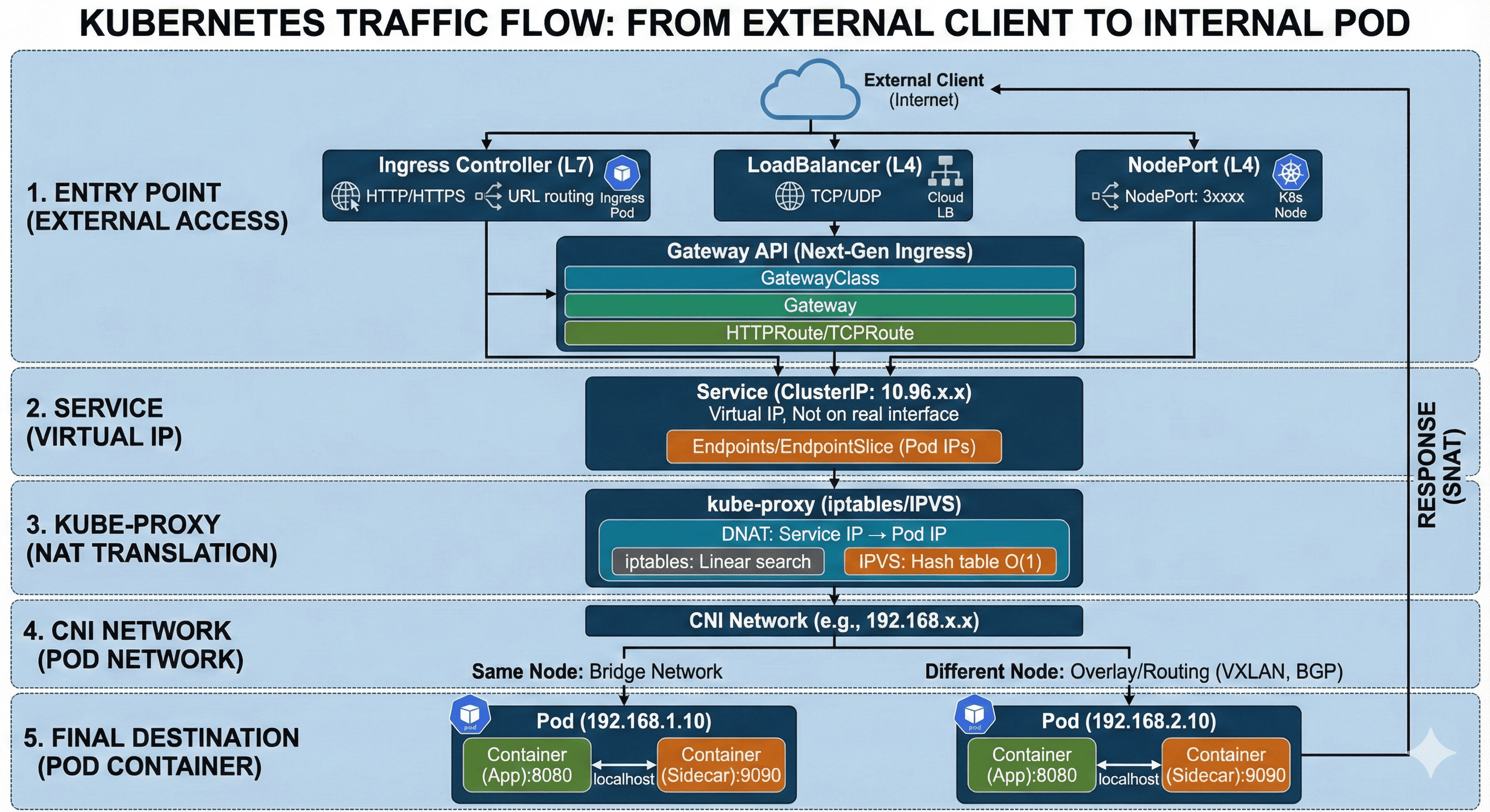
Understanding how external traffic reaches internal Pods in a Kubernetes cluster is essential for operations and troubleshooting. Incoming requests don’t simply connect directly to Pods—they traverse multiple network components before reaching their final destination.
External traffic first enters the cluster through an Ingress Controller or LoadBalancer. It’s then forwarded to a Service object’s ClusterIP, which is a virtual IP rather than an actual IP address. kube-proxy manages iptables or IPVS rules on each node, performing DNAT (Destination NAT) to transform packets destined for the Service IP into actual Pod IPs. Finally, packets are delivered to the container port through the network configured by the CNI (Container Network Interface). If the Pod resides on a different node, inter-node communication occurs through an Overlay network (such as VXLAN).
This guide provides a step-by-step analysis of the entire journey from when external traffic enters the Kubernetes cluster to when it reaches the actual container.
Complete Traffic Flow Overview
The process of external traffic reaching a Pod inside a Kubernetes cluster can be divided into five major stages.
External Client (Internet)
        │
        ▼
┌─────────────────────────────────────┐
│  Stage 1: Entry Point               │
│  - Ingress Controller (L7)          │
│  - Gateway API (L7)                 │
│  - LoadBalancer (L4)                │
│  - NodePort (specific node port)    │
└─────────────────────────────────────┘
        │
        ▼
┌─────────────────────────────────────┐
│  Stage 2: Service (Virtual IP)      │
│  - ClusterIP: 10.96.x.x             │
│  - Does not exist on actual network │
└─────────────────────────────────────┘
        │
        ▼
┌─────────────────────────────────────┐
│  Stage 3: kube-proxy (NAT)          │
│  - iptables or IPVS rules           │
│  - DNAT: Service IP → Pod IP        │
└─────────────────────────────────────┘
        │
        ▼
┌─────────────────────────────────────┐
│  Stage 4: CNI Network               │
│  - Pod Network (192.168.x.x)        │
│  - Inter-node: Overlay/Routing      │
└─────────────────────────────────────┘
        │
        ▼
┌─────────────────────────────────────┐
│  Stage 5: Final Destination         │
│  - Pod Container (targetPort)       │
└─────────────────────────────────────┘
Stage 1: Entry Point
There are four main ways for external traffic to enter a Kubernetes cluster. Each operates at a different layer and is chosen based on the intended purpose.
External Client
    │
    ▼
┌─────────────────────┐
│  Ingress Controller │ (L7) - HTTP/HTTPS
│  or                 │
│  Gateway API        │ (L7) - HTTP/HTTPS/gRPC
│  or                 │
│  LoadBalancer       │ (L4) - TCP/UDP
│  or                 │
│  NodePort           │ (specific node port)
└─────────────────────┘
Ingress Controller (L7 Load Balancer)
Ingress Controller is an L7 (Application Layer) load balancer that handles HTTP/HTTPS traffic. It performs application-level routing based on URL paths, host headers, and TLS termination.
# Ingress resource example
apiVersion: networking.k8s.io/v1
kind: Ingress
metadata:
  name: web-ingress
  annotations:
    nginx.ingress.kubernetes.io/rewrite-target: /
spec:
  ingressClassName: nginx
  rules:
  - host: app.example.com
    http:
      paths:
      - path: /api
        pathType: Prefix
        backend:
          service:
            name: api-service
            port:
              number: 80
      - path: /
        pathType: Prefix
        backend:
          service:
            name: web-service
            port:
              number: 80
  tls:
  - hosts:
    - app.example.com
    secretName: tls-secret
The packet flow for Ingress Controller is as follows:
Client (203.0.113.10)
    │
    │ HTTPS request: app.example.com/api/users
    ▼
┌───────────────────────────────────────┐
│  External LoadBalancer                │
│  (AWS ALB / GCP GLB / MetalLB)        │
│  Public IP: 34.123.45.67              │
└───────────────────────────────────────┘
    │
    │ Port 443 → NodePort or LoadBalancer IP
    ▼
┌───────────────────────────────────────┐
│  Ingress Controller Pod              │
│  (nginx-ingress / traefik / etc)     │
│  ┌─────────────────────────────────┐ │
│  │ 1. TLS Termination              │ │
│  │ 2. Host header verification     │ │
│  │ 3. URL path matching            │ │
│  │ 4. Backend Service selection    │ │
│  └─────────────────────────────────┘ │
└───────────────────────────────────────┘
    │
    │ HTTP request → ClusterIP Service
    ▼
┌───────────────────────────────────────┐
│  api-service (ClusterIP)              │
│  10.96.100.50:80                      │
└───────────────────────────────────────┘
Major Ingress Controller types include:
| Ingress Controller | Features | Use Case |
|---|---|---|
| NGINX Ingress | Most widely used, stable | General purpose |
| Traefik | Auto-configuration, Let's Encrypt integration | Small to medium scale |
| HAProxy | High performance, fine-grained settings | High traffic |
| AWS ALB Ingress | AWS native integration | AWS EKS |
| GKE Ingress | GCP native integration | GCP GKE |
| Istio Gateway | Service mesh integration | Microservices |
Gateway API (Next-Generation Ingress)
Gateway API is the next-generation version of Ingress developed by Kubernetes SIG-Network. It offers more expressive capabilities, role-based resource separation, and excellent extensibility. As of Kubernetes 1.29, Gateway, GatewayClass, and HTTPRoute have been promoted to GA (General Availability).
┌─────────────────────────────────────────────────────────────┐
│                 Gateway API Resource Hierarchy              │
├─────────────────────────────────────────────────────────────┤
│                                                             │
│  Infrastructure Admin (Cluster Operator)                    │
│  ┌─────────────────────────────────────────────────────┐    │
│  │  GatewayClass                                       │    │
│  │  - Defines Gateway implementation (nginx, envoy, etc)│   │
│  │  - Cluster-scoped resource                          │    │
│  └─────────────────────────────────────────────────────┘    │
│                          │                                  │
│                          ▼                                  │
│  Cluster Operator (Platform Team)                           │
│  ┌─────────────────────────────────────────────────────┐    │
│  │  Gateway                                            │    │
│  │  - Actual load balancer/proxy instance              │    │
│  │  - Listener (port, protocol, TLS) configuration     │    │
│  │  - Namespace-scoped resource                        │    │
│  └─────────────────────────────────────────────────────┘    │
│                          │                                  │
│                          ▼                                  │
│  Application Developer (App Team)                           │
│  ┌─────────────────────────────────────────────────────┐    │
│  │  HTTPRoute / GRPCRoute / TCPRoute / TLSRoute        │    │
│  │  - Defines traffic routing rules                    │    │
│  │  - Backend Service connection                       │    │
│  │  - Namespace-scoped resource                        │    │
│  └─────────────────────────────────────────────────────┘    │
│                                                             │
└─────────────────────────────────────────────────────────────┘
GatewayClass Example:
# Created by infrastructure admin - Using NGINX Gateway Fabric
apiVersion: gateway.networking.k8s.io/v1
kind: GatewayClass
metadata:
  name: nginx
spec:
  controllerName: gateway.nginx.org/nginx-gateway-controller
Gateway Example:
# Created by cluster operator - Actual Gateway instance
apiVersion: gateway.networking.k8s.io/v1
kind: Gateway
metadata:
  name: main-gateway
  namespace: gateway-system
spec:
  gatewayClassName: nginx
  listeners:
  - name: http
    port: 80
    protocol: HTTP
    allowedRoutes:
      namespaces:
        from: All  # Allow Routes from all namespaces
  - name: https
    port: 443
    protocol: HTTPS
    tls:
      mode: Terminate
      certificateRefs:
      - name: tls-secret
        kind: Secret
    allowedRoutes:
      namespaces:
        from: Selector
        selector:
          matchLabels:
            gateway-access: "true"
HTTPRoute Example:
# Created by application developer - Routing rules
apiVersion: gateway.networking.k8s.io/v1
kind: HTTPRoute
metadata:
  name: api-routes
  namespace: app-namespace
spec:
  parentRefs:
  - name: main-gateway
    namespace: gateway-system
  hostnames:
  - "api.example.com"
  rules:
  # /v1/* requests → api-v1-service
  - matches:
    - path:
        type: PathPrefix
        value: /v1
    backendRefs:
    - name: api-v1-service
      port: 80
      weight: 100
  # /v2/* requests → api-v2-service (canary deployment)
  - matches:
    - path:
        type: PathPrefix
        value: /v2
    backendRefs:
    - name: api-v2-stable
      port: 80
      weight: 90
    - name: api-v2-canary
      port: 80
      weight: 10
  # Header-based routing
  - matches:
    - headers:
      - name: X-Version
        value: beta
    backendRefs:
    - name: api-beta-service
      port: 80
The packet flow for Gateway API is as follows:
Client (203.0.113.10)
    │
    │ HTTPS request: api.example.com/v1/users
    ▼
┌───────────────────────────────────────┐
│  External LoadBalancer               │
│  (Cloud LB / MetalLB)                │
│  Public IP: 34.123.45.67             │
└───────────────────────────────────────┘
    │
    ▼
┌───────────────────────────────────────┐
│  Gateway (main-gateway)              │
│  ┌─────────────────────────────────┐ │
│  │ Listener: HTTPS (443)           │ │
│  │ - TLS Termination               │ │
│  │ - Host matching: api.example.com│ │
│  └─────────────────────────────────┘ │
│               │                       │
│               ▼                       │
│  ┌─────────────────────────────────┐ │
│  │ HTTPRoute Matching              │ │
│  │ - Path: /v1/* → api-v1-service │ │
│  │ - Weight-based load balancing   │ │
│  └─────────────────────────────────┘ │
└───────────────────────────────────────┘
    │
    ▼
┌───────────────────────────────────────┐
│  api-v1-service (ClusterIP)          │
│  10.96.100.50:80                     │
└───────────────────────────────────────┘
Major Gateway API Implementations:
| Implementation | Features | Status |
|---|---|---|
| NGINX Gateway Fabric | NGINX-based, enterprise support | GA |
| Envoy Gateway | Envoy proxy-based, CNCF project | GA |
| Istio | Service mesh integration, advanced traffic management | GA |
| Cilium | eBPF-based, high performance | GA |
| Traefik | Auto-configuration, easy to use | GA |
| Kong | API Gateway features integrated | GA |
| HAProxy Kubernetes Ingress | High performance, fine-grained settings | Beta |
Ingress vs Gateway API Comparison:
| Feature | Ingress | Gateway API |
|---|---|---|
| API Maturity | Stable (v1) | Stable (v1) - 1.29+ |
| Role Separation | Single resource | GatewayClass/Gateway/Route |
| Protocol Support | HTTP/HTTPS | HTTP, HTTPS, TCP, UDP, gRPC, TLS |
| Traffic Splitting | Limited (annotations) | Native support (weight) |
| Header-based Routing | Implementation-dependent | Standard spec |
| Extensibility | Annotation-based | Policy Attachment |
| Cross-namespace | Limited | Native support |
LoadBalancer (L4 Load Balancer)
LoadBalancer type Service operates at L4 (Transport Layer) and directly handles TCP/UDP traffic. In cloud environments, the CSP (Cloud Service Provider) automatically provisions the load balancer.
# LoadBalancer Service example
apiVersion: v1
kind: Service
metadata:
  name: web-service
  annotations:
    # When using AWS NLB
    service.beta.kubernetes.io/aws-load-balancer-type: nlb
    # For internal LB
    service.beta.kubernetes.io/aws-load-balancer-internal: "true"
spec:
  type: LoadBalancer
  selector:
    app: web
  ports:
  - name: http
    port: 80
    targetPort: 8080
  - name: https
    port: 443
    targetPort: 8443
The packet flow for LoadBalancer is as follows:
Client (203.0.113.10)
    │
    │ TCP connection: 34.123.45.67:80
    ▼
┌───────────────────────────────────────┐
│  Cloud Load Balancer                  │
│  (AWS NLB / GCP LB / Azure LB)        │
│  ┌─────────────────────────────────┐  │
│  │ External IP: 34.123.45.67       │  │
│  │ Health Check: /healthz          │  │
│  │ Load Balancing: Round Robin     │  │
│  └─────────────────────────────────┘  │
└───────────────────────────────────────┘
    │
    │ Traffic distribution → Each node's NodePort
    ▼
┌─────────────┐  ┌─────────────┐  ┌─────────────┐
│   Node 1    │  │   Node 2    │  │   Node 3    │
│ :30080      │  │ :30080      │  │ :30080      │
└─────────────┘  └─────────────┘  └─────────────┘
    │                  │                  │
    └──────────────────┼──────────────────┘
                       │
                       ▼
              ┌─────────────────┐
              │ ClusterIP       │
              │ 10.96.100.50:80 │
              └─────────────────┘
NodePort (Direct Node Port Exposure)
NodePort exposes a Service externally through a specific port (30000-32767) on all nodes. It’s the most basic external exposure method and serves as the foundation for LoadBalancer.
# NodePort Service example
apiVersion: v1
kind: Service
metadata:
  name: web-service
spec:
  type: NodePort
  selector:
    app: web
  ports:
  - port: 80          # Service port (used with ClusterIP)
    targetPort: 8080  # Pod container port
    nodePort: 30080   # Port opened on nodes (auto-assigned if omitted)
The packet flow for NodePort is as follows:
Client (203.0.113.10)
    │
    │ TCP connection: 10.100.1.10:30080 (Node 1 IP)
    ▼
┌───────────────────────────────────────┐
│  Node 1 (10.100.1.10)                 │
│  ┌─────────────────────────────────┐  │
│  │ kube-proxy listening on 30080   │  │
│  │                                 │  │
│  │ iptables/IPVS rules:            │  │
│  │ :30080 → ClusterIP:80           │  │
│  └─────────────────────────────────┘  │
└───────────────────────────────────────┘
    │
    │ DNAT: 10.100.1.10:30080 → 10.96.100.50:80
    ▼
┌───────────────────────────────────────┐
│  Service (ClusterIP)                  │
│  10.96.100.50:80                      │
└───────────────────────────────────────┘
Entry Point Comparison Summary
| Feature | Ingress | Gateway API | LoadBalancer | NodePort |
|---|---|---|---|---|
| OSI Layer | L7 (HTTP/HTTPS) | L7 (HTTP/HTTPS/gRPC) | L4 (TCP/UDP) | L4 (TCP/UDP) |
| TLS Termination | Supported | Supported | Separate config needed | Not supported |
| URL Routing | Supported | Supported (advanced) | Not supported | Not supported |
| Traffic Splitting | Limited | Native (weight) | Not supported | Not supported |
| Role Separation | Single resource | 3-tier separation | Single resource | Single resource |
| External IP | 1 LB IP | 1 per Gateway | 1 per Service | Node IP used |
| Cost | 1 LB | 1 LB | 1 LB per Service | Free |
| Use Case | Web applications | Complex routing, MSA | TCP services, DB | Dev/Test |
Stage 2: Service (Virtual IP)
Traffic entering through entry points is forwarded to the Service’s ClusterIP. ClusterIP is a completely virtual IP that doesn’t exist on any actual network interface.
Understanding Service Network
┌─────────────────────────────────────────────────────────────┐
│                    Kubernetes Cluster                       │
│                                                             │
│  ┌─────────────────────────────────────────────────────┐    │
│  │          Service Network (Virtual)                  │    │
│  │          CIDR: 10.96.0.0/12                         │    │
│  │                                                     │    │
│  │   ┌─────────────┐    ┌─────────────┐                │    │
│  │   │ web-service │    │ api-service │                │    │
│  │   │ 10.96.1.10  │    │ 10.96.1.20  │                │    │
│  │   └─────────────┘    └─────────────┘                │    │
│  │          │                  │                       │    │
│  │          └────────┬─────────┘                       │    │
│  │                   │                                 │    │
│  └───────────────────┼─────────────────────────────────┘    │
│                      │                                      │
│                      ▼                                      │
│  ┌─────────────────────────────────────────────────────┐    │
│  │          Pod Network (Actual)                       │    │
│  │          CIDR: 192.168.0.0/16                       │    │
│  │                                                     │    │
│  │   ┌─────────┐ ┌─────────┐ ┌─────────┐               │    │
│  │   │ Pod 1   │ │ Pod 2   │ │ Pod 3   │               │    │
│  │   │.1.10    │ │.1.11    │ │.2.10    │               │    │
│  │   └─────────┘ └─────────┘ └─────────┘               │    │
│  └─────────────────────────────────────────────────────┘    │
│                                                             │
└─────────────────────────────────────────────────────────────┘
Relationship Between Service and Endpoints
Service selects Pods through label selectors, and the selected Pods’ IPs are registered in the Endpoints (or EndpointSlice) resource.
# Service definition
apiVersion: v1
kind: Service
metadata:
  name: web-service
spec:
  selector:
    app: web      # Selects Pods with this label
  ports:
  - port: 80
    targetPort: 8080
# Check Endpoints
kubectl get endpoints web-service

# Example output
NAME          ENDPOINTS                                      AGE
web-service   192.168.1.10:8080,192.168.1.11:8080,192.168.2.10:8080   5m
# Check EndpointSlice (Kubernetes 1.21+)
kubectl get endpointslices -l kubernetes.io/service-name=web-service

# Example output
NAME                  ADDRESSTYPE   PORTS   ENDPOINTS                           AGE
web-service-abc12     IPv4          8080    192.168.1.10,192.168.1.11,192.168.2.10   5m
When a Service receives traffic, it’s forwarded to one of the Pod IPs registered in Endpoints. This process is handled by kube-proxy in Stage 3.
Stage 3: kube-proxy (NAT Transformation)
kube-proxy runs on each node and is responsible for transforming (DNAT) traffic coming to the Service IP into actual Pod IPs.
kube-proxy Operating Modes
kube-proxy can operate in three modes:
| Mode | Method | Performance | Features |
|---|---|---|---|
| iptables | iptables rules | Medium | Default mode, linear search |
| IPVS | IPVS kernel module | High | Hash table, O(1) lookup |
| userspace | Proxy process | Low | Legacy, rarely used |
# Check kube-proxy mode
kubectl get cm kube-proxy -n kube-system -o yaml | grep mode

# Example output
mode: ipvs
iptables Mode Packet Flow
Client request: 10.96.100.50:80 (Service IP)
    │
    ▼
┌───────────────────────────────────────────────────────┐
│  Node (iptables rules)                                │
│                                                       │
│  PREROUTING chain:                                    │
│  ┌─────────────────────────────────────────────────┐  │
│  │ -A PREROUTING -j KUBE-SERVICES                  │  │
│  └─────────────────────────────────────────────────┘  │
│                      │                                │
│                      ▼                                │
│  KUBE-SERVICES chain:                                 │
│  ┌─────────────────────────────────────────────────┐  │
│  │ -A KUBE-SERVICES -d 10.96.100.50/32 -p tcp      │  │
│  │    --dport 80 -j KUBE-SVC-XXXXXX                │  │
│  └─────────────────────────────────────────────────┘  │
│                      │                                │
│                      ▼                                │
│  KUBE-SVC-XXXXXX chain (load balancing):              │
│  ┌─────────────────────────────────────────────────┐  │
│  │ -A KUBE-SVC-XXXXXX -m statistic --mode random   │  │
│  │    --probability 0.33 -j KUBE-SEP-AAAA          │  │
│  │ -A KUBE-SVC-XXXXXX -m statistic --mode random   │  │
│  │    --probability 0.50 -j KUBE-SEP-BBBB          │  │
│  │ -A KUBE-SVC-XXXXXX -j KUBE-SEP-CCCC             │  │
│  └─────────────────────────────────────────────────┘  │
│                      │                                │
│                      ▼                                │
│  KUBE-SEP-AAAA chain (DNAT):                          │
│  ┌─────────────────────────────────────────────────┐  │
│  │ -A KUBE-SEP-AAAA -p tcp -j DNAT                 │  │
│  │    --to-destination 192.168.1.10:8080           │  │
│  └─────────────────────────────────────────────────┘  │
└───────────────────────────────────────────────────────┘
    │
    ▼
Destination transformed: 192.168.1.10:8080 (Pod IP)
IPVS Mode Packet Flow
IPVS mode uses the Linux kernel’s IPVS (IP Virtual Server) module to perform more efficient load balancing.
Client request: 10.96.100.50:80 (Service IP)
    │
    ▼
┌───────────────────────────────────────────────────────┐
│  Node (IPVS rules)                                    │
│                                                       │
│  kube-ipvs0 interface:                                │
│  ┌─────────────────────────────────────────────────┐  │
│  │ inet 10.96.100.50/32 scope global kube-ipvs0    │  │
│  │ (All ClusterIPs are bound)                      │  │
│  └─────────────────────────────────────────────────┘  │
│                      │                                │
│                      ▼                                │
│  IPVS Virtual Server:                                 │
│  ┌─────────────────────────────────────────────────┐  │
│  │ TCP  10.96.100.50:80 rr                         │  │
│  │   -> 192.168.1.10:8080    Masq    1    0    0   │  │
│  │   -> 192.168.1.11:8080    Masq    1    0    0   │  │
│  │   -> 192.168.2.10:8080    Masq    1    0    0   │  │
│  └─────────────────────────────────────────────────┘  │
│                      │                                │
│                      ▼                                │
│  Hash table lookup → Real Server selection → DNAT     │
└───────────────────────────────────────────────────────┘
    │
    ▼
Destination transformed: 192.168.1.10:8080 (Pod IP)
# Check IPVS rules
sudo ipvsadm -Ln

# Example output
IP Virtual Server version 1.2.1 (size=4096)
Prot LocalAddress:Port Scheduler Flags
  -> RemoteAddress:Port           Forward Weight ActiveConn InActConn
TCP  10.96.100.50:80 rr
  -> 192.168.1.10:8080            Masq    1      0          0
  -> 192.168.1.11:8080            Masq    1      0          0
  -> 192.168.2.10:8080            Masq    1      0          0
DNAT and SNAT in Detail
Let’s examine the NAT transformation performed by kube-proxy in detail:
Request Packet (DNAT - Destination NAT)
━━━━━━━━━━━━━━━━━━━━━━━━━━━━━━━━━━━━━━━

[Original Packet]
┌─────────────────────────────────────┐
│ Src IP: 203.0.113.10 (Client)       │
│ Dst IP: 10.96.100.50 (Service)      │
│ Src Port: 54321                     │
│ Dst Port: 80                        │
└─────────────────────────────────────┘
                │
                │ DNAT performed
                ▼
[Transformed Packet]
┌─────────────────────────────────────┐
│ Src IP: 203.0.113.10 (Client)       │
│ Dst IP: 192.168.1.10 (Pod)          │  ← Destination changed
│ Src Port: 54321                     │
│ Dst Port: 8080                      │  ← Port also changed
└─────────────────────────────────────┘


Response Packet (SNAT - Source NAT)
━━━━━━━━━━━━━━━━━━━━━━━━━━━━━━━━━━━━

[Original Response]
┌─────────────────────────────────────┐
│ Src IP: 192.168.1.10 (Pod)          │
│ Dst IP: 203.0.113.10 (Client)       │
│ Src Port: 8080                      │
│ Dst Port: 54321                     │
└─────────────────────────────────────┘
                │
                │ SNAT performed (conntrack-based)
                ▼
[Transformed Response]
┌─────────────────────────────────────┐
│ Src IP: 10.96.100.50 (Service)      │  ← Source changed
│ Dst IP: 203.0.113.10 (Client)       │
│ Src Port: 80                        │  ← Port also changed
│ Dst Port: 54321                     │
└─────────────────────────────────────┘
conntrack (Connection Tracking) matches request and response packets to perform the correct NAT reverse transformation.
Stage 4: CNI Network
Packets transformed by DNAT are delivered to the actual Pod through the network configured by the CNI (Container Network Interface).
Role of CNI
CNI plugins perform the following roles:
- Create network interface (veth pair) for Pods
- Assign IP addresses to Pods (IPAM)
- Set up communication paths between Pods within a node
- Configure Overlay/Routing for inter-node Pod communication
┌─────────────────────────────────────────────────────────────┐
│  Node 1 (10.100.1.10)                                       │
│  Pod CIDR: 192.168.1.0/24                                   │
│                                                             │
│  ┌───────────────┐    ┌───────────────┐                     │
│  │    Pod A      │    │    Pod B      │                     │
│  │ 192.168.1.10  │    │ 192.168.1.11  │                     │
│  │    ┌─────┐    │    │    ┌─────┐    │                     │
│  │    │eth0 │    │    │    │eth0 │    │                     │
│  │    └──┬──┘    │    │    └──┬──┘    │                     │
│  └───────┼───────┘    └───────┼───────┘                     │
│          │                    │                             │
│          │ veth pair          │ veth pair                   │
│          │                    │                             │
│  ┌───────┴────────────────────┴───────┐                     │
│  │           cni0 (Bridge)            │                     │
│  │           192.168.1.1              │                     │
│  └────────────────┬───────────────────┘                     │
│                   │                                         │
│  ┌────────────────┴───────────────────┐                     │
│  │         eth0 (Node NIC)            │                     │
│  │         10.100.1.10                │                     │
│  └────────────────┬───────────────────┘                     │
└───────────────────┼─────────────────────────────────────────┘
                    │
                    │  Overlay Network (VXLAN/Geneve)
                    │  or BGP Routing
                    │
┌───────────────────┼─────────────────────────────────────────┐
│  Node 2 (10.100.1.11)                                       │
│  Pod CIDR: 192.168.2.0/24                                   │
│                   │                                         │
│  ┌────────────────┴───────────────────┐                     │
│  │         eth0 (Node NIC)            │                     │
│  │         10.100.1.11                │                     │
│  └────────────────┬───────────────────┘                     │
│                   │                                         │
│  ┌────────────────┴───────────────────┐                     │
│  │           cni0 (Bridge)            │                     │
│  │           192.168.2.1              │                     │
│  └───────┬────────────────────┬───────┘                     │
│          │                    │                             │
│  ┌───────┴───────┐    ┌───────┴───────┐                     │
│  │    Pod C      │    │    Pod D      │                     │
│  │ 192.168.2.10  │    │ 192.168.2.11  │                     │
│  └───────────────┘    └───────────────┘                     │
└─────────────────────────────────────────────────────────────┘
Major CNI Plugin Comparison
| CNI | Network Mode | Features | Use Case |
|---|---|---|---|
| Calico | BGP/VXLAN | High performance, Network Policy | On-premises, Cloud |
| Flannel | VXLAN/host-gw | Simple setup, lightweight | Small clusters |
| Cilium | eBPF | High performance, L7 policies | Large scale, Security-focused |
| AWS VPC CNI | Native VPC | AWS native, high performance | AWS EKS |
| Weave | VXLAN | Encryption support, simple | Multi-cloud |
Same Node vs Different Node Communication
Pod-to-Pod communication within the same node:
Pod A (192.168.1.10) → Pod B (192.168.1.11)

┌─────────────────────────────────────┐
│  Node 1                             │
│                                     │
│  Pod A          Bridge         Pod B│
│  ┌─────┐       ┌─────┐       ┌─────┐│
│  │eth0 │──veth─│cni0 │─veth──│eth0 ││
│  └─────┘       └─────┘       └─────┘│
│                                     │
│  Packet path: eth0 → veth → cni0 → veth → eth0
│  (Does not leave the node)          │
└─────────────────────────────────────┘
Pod-to-Pod communication across different nodes:
Pod A (192.168.1.10) → Pod C (192.168.2.10)

┌─────────────┐                      ┌─────────────┐
│   Node 1    │                      │   Node 2    │
│             │                      │             │
│  ┌───────┐  │    Overlay/BGP       │  ┌───────┐  │
│  │ Pod A │  │  ┌──────────────┐    │  │ Pod C │  │
│  │.1.10  │──┼──│ VXLAN Tunnel │────┼──│.2.10  │  │
│  └───────┘  │  │ or BGP       │    │  └───────┘  │
│             │  └──────────────┘    │             │
└─────────────┘                      └─────────────┘

Packet path:
1. Pod A eth0 → veth → cni0 → Node1 eth0
2. Node1 eth0 → [VXLAN encapsulation] → Physical network
3. Physical network → Node2 eth0 → [VXLAN decapsulation]
4. cni0 → veth → Pod C eth0
Stage 5: Final Destination (Pod Container)
Packets delivered through the CNI network finally reach the Container inside the Pod.
┌──────────────────────────────────────────────────────────────┐
│  Pod (192.168.1.10)                                          │
│  ┌─────────────────────────────────────────────────────┐     │
│  │  Network Namespace                                  │     │
│  │                                                     │     │
│  │  ┌─────────┐                                        │     │
│  │  │  eth0   │ ← Packet received (dst: 192.168.1.10:8080) │ │
│  │  └────┬────┘                                        │     │
│  │       │                                             │     │
│  │       │ iptables/network stack                      │     │
│  │       │                                             │     │
│  │       ▼                                             │     │
│  │  ┌─────────────────────────────────────────────┐    │     │
│  │  │              localhost                      │    │     │
│  │  │                                             │    │     │
│  │  │  ┌─────────────┐    ┌─────────────┐         │    │     │
│  │  │  │ Container 1 │    │ Container 2 │         │    │     │
│  │  │  │ (App)       │    │ (Sidecar)   │         │    │     │
│  │  │  │ :8080       │    │ :9090       │         │    │     │
│  │  │  └─────────────┘    └─────────────┘         │    │     │
│  │  │                                             │    │     │
│  │  │  Containers in same Pod communicate via localhost  │   │
│  │  └─────────────────────────────────────────────┘    │     │
│  └─────────────────────────────────────────────────────┘     │
└──────────────────────────────────────────────────────────────┘
Containers within a Pod share the same Network Namespace, allowing them to communicate with each other via localhost.
Complete Packet Flow Summary
Here’s a consolidated diagram summarizing the complete packet flow from external client to Pod:
┌─────────────────────────────────────────────────────────────────────────┐
│                     Complete Packet Flow Summary                        │
└─────────────────────────────────────────────────────────────────────────┘

External Client (203.0.113.10)
    │
    │ ① HTTPS request: app.example.com/api (203.0.113.10:54321 → 34.123.45.67:443)
    ▼
┌─────────────────────────────────────┐
│ Stage 1: Ingress/Gateway            │
│ - TLS Termination                   │
│ - Host/Path routing                 │
│ - Backend Service selection         │
└─────────────────────────────────────┘
    │
    │ ② HTTP request: (Ingress Pod IP:port → 10.96.100.50:80)
    ▼
┌─────────────────────────────────────┐
│ Stage 2: Service (ClusterIP)        │
│ - Virtual IP: 10.96.100.50          │
│ - Endpoints: Pod IP list management │
└─────────────────────────────────────┘
    │
    │ ③ DNAT performed (kube-proxy)
    ▼
┌─────────────────────────────────────┐
│ Stage 3: kube-proxy (iptables/IPVS) │
│ - 10.96.100.50:80 → 192.168.1.10:8080│
│ - Load balancing (RR/LC/SH)         │
│ - conntrack recording               │
└─────────────────────────────────────┘
    │
    │ ④ Pod Network delivery
    ▼
┌─────────────────────────────────────┐
│ Stage 4: CNI Network                │
│ - Same node: Bridge traversal       │
│ - Different node: Overlay/Routing   │
└─────────────────────────────────────┘
    │
    │ ⑤ Container port reached
    ▼
┌─────────────────────────────────────┐
│ Stage 5: Pod Container              │
│ - 192.168.1.10:8080                 │
│ - Application processing            │
└─────────────────────────────────────┘
    │
    │ ⑥ Response (SNAT applied in reverse)
    ▼
External Client (203.0.113.10)
Packet Analysis Lab
Let’s learn how to verify packet flow in an actual environment.
Test Environment Setup
# Create test namespace
kubectl create namespace traffic-test

# Deploy backend Pods
kubectl create deployment nginx --image=nginx:latest --replicas=3 -n traffic-test

# Create Service
kubectl expose deployment nginx --port=80 --target-port=80 --name=nginx-service -n traffic-test

# Create client Pod
kubectl run client-pod --image=nicolaka/netshoot -n traffic-test --command -- sleep infinity
Packet Capture at Each Stage
# 1. Check Service IP
SERVICE_IP=$(kubectl get svc nginx-service -n traffic-test -o jsonpath='{.spec.clusterIP}')
echo "Service IP: $SERVICE_IP"

# 2. Check IPVS rules on node
ssh <node> "sudo ipvsadm -Ln | grep -A 5 $SERVICE_IP"

# 3. tcpdump in client Pod
kubectl exec -it client-pod -n traffic-test -- tcpdump -i any -nn host $SERVICE_IP

# 4. tcpdump on node (verify before/after DNAT)
ssh <node> "sudo tcpdump -i any -nn host $SERVICE_IP"

# 5. tcpdump in backend Pod
kubectl exec -it <nginx-pod> -n traffic-test -- tcpdump -i any -nn port 80
Traffic Generation and Analysis
# Generate request from client Pod
kubectl exec -it client-pod -n traffic-test -- curl -v http://nginx-service

# Verify load balancing with multiple requests
kubectl exec -it client-pod -n traffic-test -- bash -c "for i in {1..10}; do curl -s http://nginx-service | head -1; done"
Troubleshooting Guide
Here’s a summary of common issues and solutions for external traffic flow.
Problem 1: Cannot Connect to Service
# Diagnostic sequence
# 1. Verify Service exists
kubectl get svc -n <namespace>

# 2. Check Endpoints (verify Pods are registered)
kubectl get endpoints <service-name> -n <namespace>

# 3. Check Pod status
kubectl get pods -n <namespace> -l <selector>

# 4. Check kube-proxy status
kubectl get pods -n kube-system -l k8s-app=kube-proxy

# 5. Check IPVS/iptables rules
sudo ipvsadm -Ln | grep <service-ip>
Problem 2: Ingress/Gateway Not Working
# 1. Check Ingress Controller Pod status
kubectl get pods -n ingress-nginx

# 2. Verify Ingress resource
kubectl describe ingress <ingress-name> -n <namespace>

# 3. Check Ingress Controller logs
kubectl logs -n ingress-nginx -l app.kubernetes.io/name=ingress-nginx

# 4. Test backend Service connection
kubectl exec -it <ingress-pod> -n ingress-nginx -- curl http://<service-ip>
Problem 3: Intermittent Connection Failures
# 1. Check backend Pod status (Readiness)
kubectl get pods -o wide | grep -v Running

# 2. Check EndpointSlice status
kubectl get endpointslices -l kubernetes.io/service-name=<service>

# 3. Check conntrack table
sudo conntrack -L -d <service-ip> | head -20

# 4. Check network policies
kubectl get networkpolicies -n <namespace>
Conclusion
This guide provided a step-by-step analysis of the complete process from when external traffic enters a Kubernetes cluster to when it reaches the final Pod.
Key Takeaways
Choosing Entry Points
- Ingress Controller: Web applications requiring L7 routing, TLS termination, URL-based routing
- Gateway API: Microservice environments requiring complex routing, traffic splitting, role-based management (next-generation standard)
- LoadBalancer: L4 level TCP/UDP service exposure
- NodePort: Development/test environments or direct external load balancer integration
Gateway API Advantages
- Role-based resource separation (GatewayClass → Gateway → Route)
- Native traffic splitting (weight-based canary deployments)
- Multi-protocol support (HTTP, HTTPS, gRPC, TCP, UDP)
- Cross-namespace routing support
- Standardized extension method (Policy Attachment)
Role of Service
- ClusterIP is a virtual IP that doesn’t exist on actual networks
- Endpoints/EndpointSlice manage actual Pod IP lists
- Dynamic Pod selection through label selectors
kube-proxy NAT Transformation
- Performs DNAT: Service IP → Pod IP
- iptables mode: Linear search, suitable for small clusters
- IPVS mode: Hash table-based O(1) lookup, suitable for large clusters
- Response packet SNAT through conntrack
CNI Network
- Assigns network interfaces and IPs to Pods
- Same node: Direct communication through Bridge
- Different nodes: Overlay (VXLAN) or BGP Routing
With this understanding, you can systematically analyze and resolve Kubernetes network issues. Using tcpdump for packet analysis and verifying the status of each component is crucial for accurately identifying the root cause of problems.
Reference
- Kubernetes Documentation - Service
- Kubernetes Documentation - Ingress
- Kubernetes Documentation - Ingress Controllers
- Kubernetes Gateway API Documentation
- Kubernetes Gateway API - Getting Started
- NGINX Gateway Fabric Documentation
- Envoy Gateway Documentation
- Kubernetes Documentation - Network Policies
- Kubernetes Documentation - Cluster Networking
- NGINX Ingress Controller Documentation
- Calico Documentation - About Kubernetes Networking
- Cilium Documentation - Kubernetes Network Policy
- AWS Load Balancer Controller Documentation
- LVS (Linux Virtual Server) Documentation

Comments