15 min to read
Virtual Bridge Mode Networking: Transparent Layer 2 Connectivity in Virtualized Environments
Understanding how virtual machines achieve seamless integration with physical networks through bridge mode networking
Introduction to Bridge Mode Networking
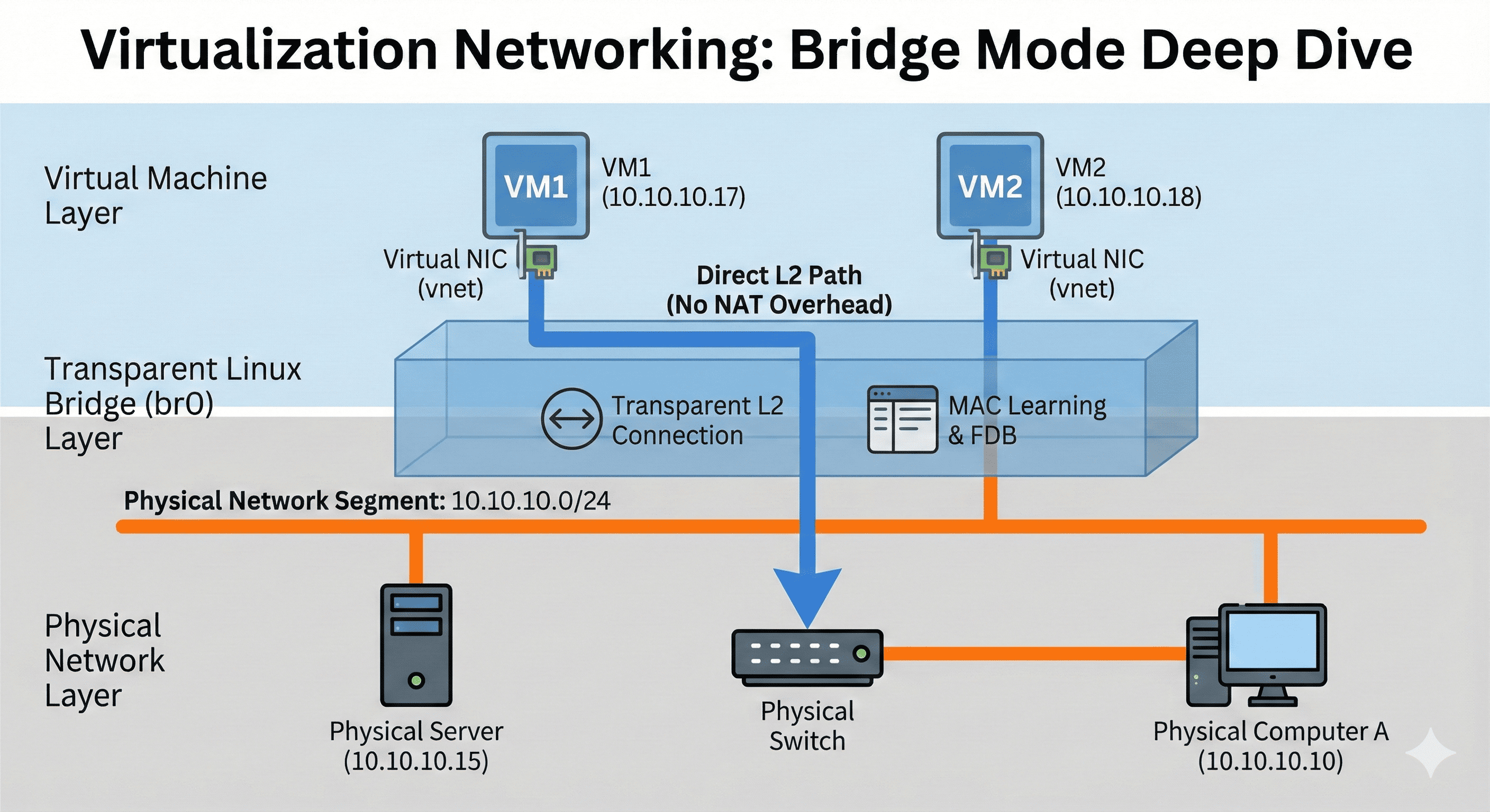
Bridge mode is a fundamental networking technology in virtualized environments that creates transparent connectivity between virtual machines and physical networks.
Operating at the OSI Layer 2 (Data Link Layer), this sophisticated network virtualization mechanism goes far beyond the simple “bridge” concept its name suggests.
Many system administrators choose bridge mode but often don’t fully understand what it means when VMs “appear to be directly connected to the physical network,” “receive IP addresses from the same network segment,” or “provide transparent L2 connectivity.”
This article will explore bridge mode from technical fundamentals to practical implementation, addressing key questions such as:
- The specific mechanism that makes VMs appear as "physical devices"
- Network segment concepts and real-world applications
- Technical advantages and limitations of L2 transparency
- MAC address learning and FDB (Forwarding Database) operations
- Fundamental differences from NAT mode and performance comparisons
- Practical IP management, security, and performance optimization strategies
Understanding “Direct Physical Network Connection”
When we say VMs “appear directly connected to the physical network,” this refers to how they are perceived by network infrastructure rather than their actual physical connectivity.
Traditional Physical Environment vs Bridge Mode
Physical Network Topology
Physical Switch
    ├── Computer A (10.10.10.10)
    ├── Computer B (10.10.10.11)
    ├── Computer C (10.10.10.12)
    └── Server     (10.10.10.15)
Bridge Mode Virtual Environment
Physical Switch
    ├── Computer A (10.10.10.10)
    ├── Computer B (10.10.10.11)
    ├── Computer C (10.10.10.12)
    └── Host Server (10.10.10.15)
            └── Linux Bridge (br0)
                    ├── VM1 (10.10.10.17) ← Appears as direct participant
                    ├── VM2 (10.10.10.18) ← Appears as direct participant
                    └── VM3 (10.10.10.19) ← Appears as direct participant
Key Technical Characteristics
From the physical switch's viewpoint, VMs appear as independent devices because:
- Unique MAC addresses: Each VM has its own distinct MAC address
- Switch table entries: Physical switch registers VM MAC addresses in its forwarding table
- ARP table presence: VMs appear as individual entries in network ARP tables
- Independent network identity: Each VM maintains its own network identity
Network Segment Unification
“Same network segment” refers to VMs sharing the identical broadcast domain, IP subnet, and VLAN as physical devices, enabling direct communication without routing.
Broadcast Domain Characteristics
A network segment encompasses:
- Broadcast domain: The scope where broadcast packets can reach
- IP subnet: Range of IP addresses sharing the same subnet mask
- VLAN: Logically separated network groups
Practical Network Configuration Example
# Physical Environment Network Segment
Network: 10.10.10.0/24
├── Gateway: 10.10.10.1
├── Physical Computer A: 10.10.10.10
├── Physical Computer B: 10.10.10.11
├── Host Server: 10.10.10.15
└── Available Range: 10.10.10.2-254

# Bridge Mode VM Integration
Network: 10.10.10.0/24 (Same segment!)
├── Gateway: 10.10.10.1 (Same gateway!)
├── Physical Computer A: 10.10.10.10
├── Physical Computer B: 10.10.10.11
├── Host Server: 10.10.10.15
├── VM1: 10.10.10.17 ← Same subnet
├── VM2: 10.10.10.18 ← Same subnet
└── VM3: 10.10.10.19 ← Same subnet
Communication Flow Benefits
Why This Matters
# VM to physical device direct communication (no routing)
VM1 (10.10.10.17) → Computer A (10.10.10.10)  # Same segment, direct communication

# If using NAT mode instead
VM1 (192.168.122.17) → NAT Gateway → Computer A (10.10.10.10)  # Routing required
Layer 2 Transparent Connectivity
“L2 transparent connectivity” means the bridge operates at the Data Link Layer (Layer 2), making its presence invisible to higher network layers while facilitating frame forwarding based on MAC addresses.
OSI Layer Context
OSI 7-Layer Model and Bridge Operation
L7 - Application  │ HTTP, FTP, SSH
L6 - Presentation │ Encryption, Compression
L5 - Session      │ Session Management
L4 - Transport    │ TCP, UDP
L3 - Network      │ IP, Routing
L2 - Data Link    │ ← Bridge operates here!
L1 - Physical     │ Cables, Signals
Bridge Operations at L2
MAC Address Learning Process
# Bridge's FDB (Forwarding Database)
Port 1 (eno1) ←→ Physical Switch
Port 2 (vnet1) ←→ VM1 (MAC: 52:54:00:12:34:56)
Port 3 (vnet2) ←→ VM2 (MAC: 52:54:00:12:34:57)

# Learning Process
1. VM1 sends packet → Bridge learns "Port 2 has 52:54:00:12:34:56"
2. Physical switch learns "Host Server port has 52:54:00:12:34:56"
3. Subsequent packets to this MAC are forwarded to correct port
Transparency Characteristics
- Higher layer invisibility: L3+ layers don't see the bridge's existence
- No IP routing required: Devices recognize each other as same network
- MAC address preservation: No address translation (unlike NAT)
- Direct frame forwarding: Minimal processing overhead
Detailed Operation Simulation
Let’s trace through a complete communication scenario: VM1 pinging a physical computer to understand the technical mechanisms involved.
Step 1: ARP Request (Address Resolution Protocol)
ARP Broadcast Flow
VM1 (10.10.10.17): "What's the MAC address of 10.10.10.10?"

# ARP broadcast packet flow
VM1 → vnet1 → Bridge br0 → eno1 → Physical Switch → All ports (broadcast)
                 ↑
          [L2 transparent forwarding]
Step 2: ARP Response
ARP Response Flow
Computer A (10.10.10.10): "My MAC is aa:bb:cc:dd:ee:ff!"

# ARP response packet flow
Computer A → Physical Switch → eno1 → Bridge br0 → vnet1 → VM1
                                        ↑
                            [MAC address learning and forwarding]
Step 3: Actual Ping Packet
ICMP Ping Communication
# Now VM1 knows Computer A's MAC address
VM1 → [Dest MAC: aa:bb:cc:dd:ee:ff, Src MAC: 52:54:00:12:34:56]
    → Bridge → Physical Switch → Computer A

# Bridge processing steps
1. Packet reception: Receive packet from vnet1
2. Destination lookup: Which port has aa:bb:cc:dd:ee:ff?
3. FDB consultation: aa:bb:cc:dd:ee:ff is on Port 1 (eno1)
4. Forwarding: Send packet to eno1
Bridge Mode vs Other Networking Modes
Understanding the differences between bridge mode and other virtualization networking modes helps clarify the specific advantages and use cases for each approach.
NAT Mode Comparison
| Aspect | NAT Mode | Bridge Mode |
|---|---|---|
| Network Segment | Separate private network (192.168.122.x) | Same as physical network (10.10.10.x) |
| Communication Path | VM → NAT Gateway → Physical Device | VM ↔ Physical Device (Direct L2) |
| IP Translation | Required at L3 layer | None required |
| External Visibility | VMs hidden behind host IP | VMs directly visible on network |
Physical Switch Perspective
MAC Address Table in NAT Mode
MAC Address         Port    VLAN
aa:bb:cc:dd:ee:ff   1       1     # Computer A
90:5a:08:74:aa:21   3       1     # Host Server only visible
MAC Address Table in Bridge Mode
MAC Address         Port    VLAN
aa:bb:cc:dd:ee:ff   1       1     # Computer A
90:5a:08:74:aa:21   3       1     # Host Server
52:54:00:12:34:56   3       1     # VM1 (via Host Server port)
52:54:00:12:34:57   3       1     # VM2 (via Host Server port)
Practical Implementation Considerations
Real-world deployment of bridge mode networking requires careful consideration of IP management, security policies, and performance optimization.
IP Address Management
DHCP Server Integration
# Physical network DHCP server allocates IPs to VMs
DHCP Pool: 10.10.10.100-200
├── Computer A: 10.10.10.10 (Static)
├── Host Server: 10.10.10.15 (Static)
├── VM1: 10.10.10.17 (DHCP assigned)
├── VM2: 10.10.10.18 (DHCP assigned)
└── Available: 10.10.10.100-200
- Prevent IP conflicts: Avoid duplicate IPs between VMs and physical devices
- Manage DHCP ranges: Reserve dedicated IP ranges for VMs
- DNS registration: VMs can be registered in DNS like physical devices
- IP tracking: Maintain inventory of VM IP assignments
Security Considerations
Firewall Policy Application
# Physical network firewall policies apply to VMs
iptables -A FORWARD -s 10.10.10.17 -d 10.10.10.10 -j ACCEPT

# VM-to-VM communication control
iptables -A FORWARD -s 10.10.10.17 -d 10.10.10.18 -j DROP
- Direct network exposure: VMs are directly accessible from physical network
- Unified security policies: Apply network security policies to VMs
- VLAN segmentation: Use VLAN tagging for additional isolation
- Microsegmentation: Implement fine-grained network controls
Performance Characteristics
Performance Advantages
# Shorter packet path
VM1 → Bridge → Physical NIC → Network

# vs NAT mode
VM1 → NAT → iptables → Routing → Physical NIC → Network
Measured Performance Differences
# Bridge mode latency
ping 10.10.10.10
# Average: 0.2ms

# NAT mode latency
ping 10.10.10.10
# Average: 0.5ms (NAT processing overhead)
Configuration and Implementation
Proper bridge configuration involves multiple steps from creating the bridge interface to configuring VM networking and performance optimization.
Bridge Creation and Setup
Manual Bridge Configuration
# Create bridge
sudo brctl addbr br0

# Add physical interface to bridge
sudo brctl addif br0 eno1

# Move IP configuration from physical interface to bridge
sudo ip addr del 10.10.10.15/24 dev eno1
sudo ip addr add 10.10.10.15/24 dev br0

# Bring up the bridge
sudo ip link set br0 up
Persistent Configuration with Netplan
Netplan Configuration (/etc/netplan/01-netcfg.yaml)
network:
  version: 2
  ethernets:
    eno1:
      dhcp4: false
  bridges:
    br0:
      interfaces: [eno1]
      addresses: [10.10.10.15/24]
      routes:
        - to: default
          via: 10.10.10.1
      nameservers:
        addresses: [8.8.8.8]
      parameters:
        stp: false
        forward-delay: 0
Libvirt Network Definition
Libvirt Bridge Network Configuration
<network>
  <name>br0-network</name>
  <forward mode='bridge'/>
  <bridge name='br0'/>
  <!-- No DHCP configuration: Use physical network DHCP -->
</network>
VM Network Interface Configuration
VM Interface Configuration
<interface type='bridge'>
  <source bridge='br0'/>
  <model type='virtio'/>
  <!-- MAC address auto-generated or manually specified -->
  <mac address='52:54:00:12:34:56'/>
  <!-- Multi-queue performance optimization -->
  <driver name='vhost' queues='4'/>
</interface>
Monitoring and Troubleshooting
Bridge Status Monitoring
Bridge Monitoring Commands
# Bridge status verification
brctl show
bridge link show

# FDB table inspection
bridge fdb show br br0

# Performance statistics
cat /sys/class/net/br0/statistics/rx_packets
cat /sys/class/net/br0/statistics/tx_packets

# STP optimization for simple environments
sudo brctl stp br0 off
echo 0 > /sys/class/net/br0/bridge/forward_delay
Common Issues and Solutions
VM Not Receiving IP Address
# Verify DHCP requests reach physical network
sudo tcpdump -i br0 port 67 or port 68

# Check bridge configuration
ip link show br0
brctl showmacs br0
VM-to-VM Communication Issues
# Verify MAC address learning in bridge FDB
bridge fdb show br br0 | grep 52:54:00

# Check iptables forwarding rules
iptables -L FORWARD -v -n
Performance Degradation
# Network queue configuration
ethtool -l eno1

# CPU utilization monitoring
top -p $(pgrep -f "qemu.*vm-name")

# Interrupt distribution verification
cat /proc/interrupts | grep eno1
When to Choose Bridge Mode
Understanding the appropriate use cases for bridge mode versus other networking approaches ensures optimal infrastructure design decisions.
Bridge Mode Ideal Scenarios
-
External service accessibility
VMs need to be directly accessible from external networks -
High-performance requirements
Network-intensive applications requiring minimal latency -
Hybrid environments
Consistent networking between physical servers and VMs -
Simple network architecture
Avoiding complex NAT configurations
NAT Mode Preferred Scenarios
- Development/testing environments: Internal isolation without external exposure
- Security-first approaches: VM isolation from physical network
- IP address conservation: Limited IP address availability
Future Evolution and Advanced Technologies
Bridge mode continues to evolve alongside modern infrastructure trends, integrating with container orchestration, SDN, and microservices architectures.
Modern Infrastructure Integration
- Kubernetes CNI: Container Network Interface implementations based on bridge principles
- OpenStack Neutron: Cloud networking solutions extending bridge concepts
- SR-IOV combinations: High-performance networking with hardware acceleration
- DPDK integration: Data Plane Development Kit for optimized packet processing
Conclusion
Bridge mode networking provides transparent Layer 2 connectivity that seamlessly integrates virtual machines with physical network infrastructure. Its fundamental operating principles make it an essential technology for understanding modern virtualized networking.
- Transparent networking: VMs appear as independent devices to physical switches
- Unified network segments: VMs and physical devices share the same subnet for direct communication
- L2 operation: MAC address learning and frame forwarding provide transparency to higher layers
- Performance optimization: Lower latency and higher throughput compared to NAT modes
- Comprehensive considerations: Requires holistic approach to IP management, security, and performance
- Future compatibility: Foundation for modern cloud and container networking technologies
Understanding bridge mode’s fundamental principles is essential for leveraging advanced networking technologies like SR-IOV, DPDK, and Open vSwitch (OVS) that build upon these core concepts.
As virtualization technology continues evolving, bridge mode remains a critical foundation for high-performance, scalable network infrastructure.

Comments